Hi there.
That post is a general overview of diaphragm compressor for H2 (hydrogen) 400 bar / 10 Nm3/h.
Probably, it’s the best solution for high pressure gas tanks filling and small hydrogen fueling stations for commercial application – for trucks, buses and others.
Project information
The customer has been developing Hydrogen generators and turnkey solutions for Hydrogen fueling stations for commercial applications during last 6 years.
They asked us about compressor solution for H2 (99.99%).
They didn’t have enough experience and skills with high pressure compressors or hydrogen compressors before. After some technical discussions the model 10 Nm3/h with final pressure 400 bar (5800 psi) was selected as main solution for H2 fueling station.
About compressor
Diaphragm compressor for Hydrogen 400 bar / 10 Nm3h
and
Diaphragm compressor for Hydrogen
and
Diaphragm compressor for H2
Main technical parameters are shown in the table below:
| Model | DC 1-10/10-400-H2 |
| Compressor type | Diaphragm oil-free compressor |
| Inlet pressure (bar g) | 10 |
| Outlet pressure (bar g) | 400 |
| Inlet gas temperature (°С) | -10…+40 |
| Pressure dew point (°С) | –
gas is dry |
| Capacity (Nm3/h) | 10 |
| Gas | H2 (99.99%) |
| Cooling | water |
| Cooling water temperature (°С) | + 1 … + 32 |
| Cooling water capacity (m3/h) | 0.5 |
| Cooling water pressure (bar g) | ≤ 6 |
| Ambient temperature (°С) | + 1 … + 45 |
| Motor power 400/3/50 (kW) | 5.5 |
| Real power consumption (kW) | 7.5 |
| Control panel | Included as separate unit |
| Implosion protection (by motor) | 1Exd IIC T4 |
| Dimensions LхWхH (мм) | 1450х830х1240 |
| Weight (kg) | 610 |
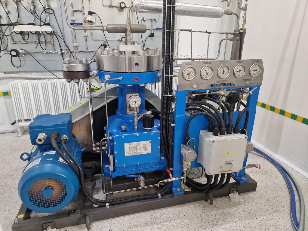
2 stage oil free diaphragm block is the main part. It consists of crankcase with main shaft and bearings, connecting rods with pistons, oil lubrication system and two diaphragm heads.
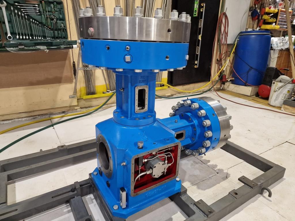
2 stage diaphragm compressor block L-type
Standard compressor’s scope of supply
The following is included:
- 2 stages / 2 cylinders compressor block
- crankcase breather
- electric motor
- motor drive pulley
- v-belts
- drive guard
- inlet gas port
- baseplate with 4 holes
- manometers (6 pieces are installed on compressor + 6 pieces as spare set)
- inlet gas pressure sensor
- outlet gas pressure sensor
- crank case oil pressure sensor
- outlet gas temperature (resistance temperature detector)
- non-return valve for final gas delivery (resistance temperature detector)
- safety valve for final gas delivery
- interstage and final gas cooler
- pressure relays to control the diaphragm rapture
- tubes “inside” compressor
- terminal box
- electrical connections to terminal box “inside” compressor
- control panel as separate unit for installation in the hazardous area
- water cooling
- auto oil pressure setting in compressor
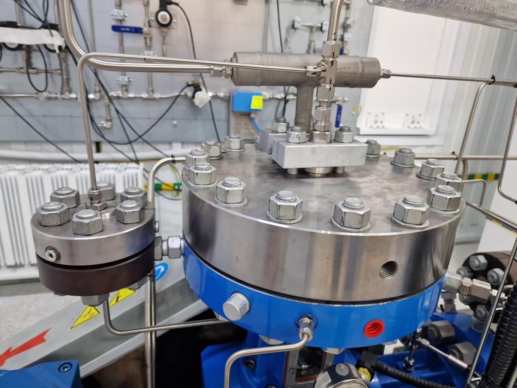
Compressor has interstage and final coolers, where the gas is cooled.
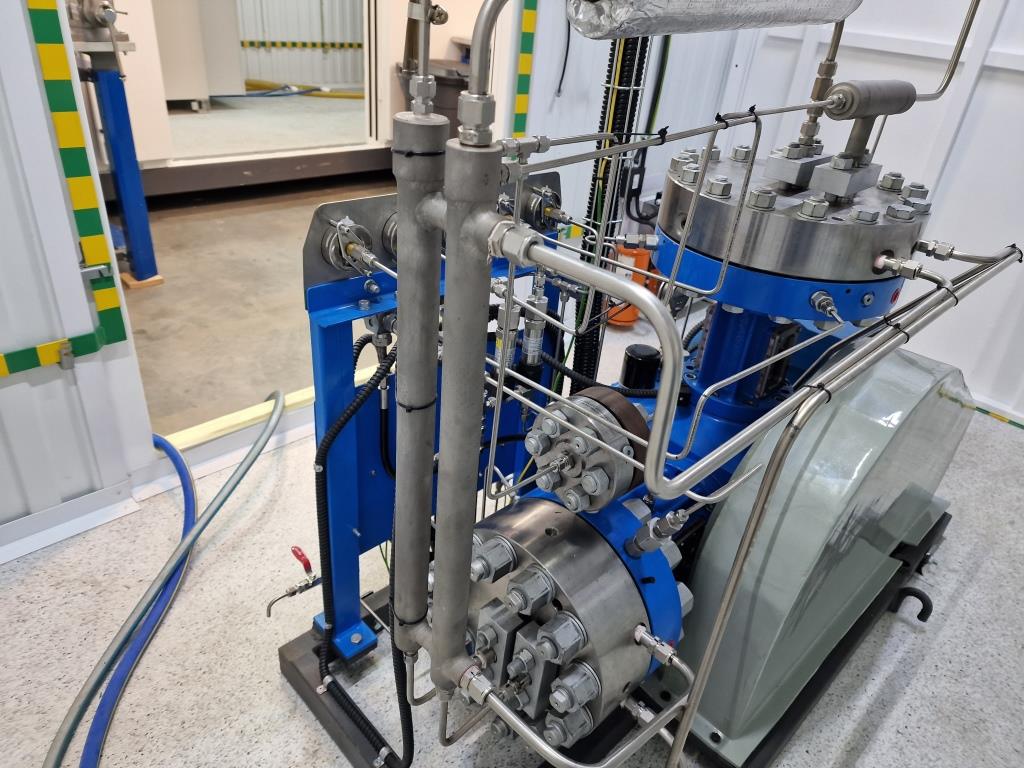
Interstage and final coolers
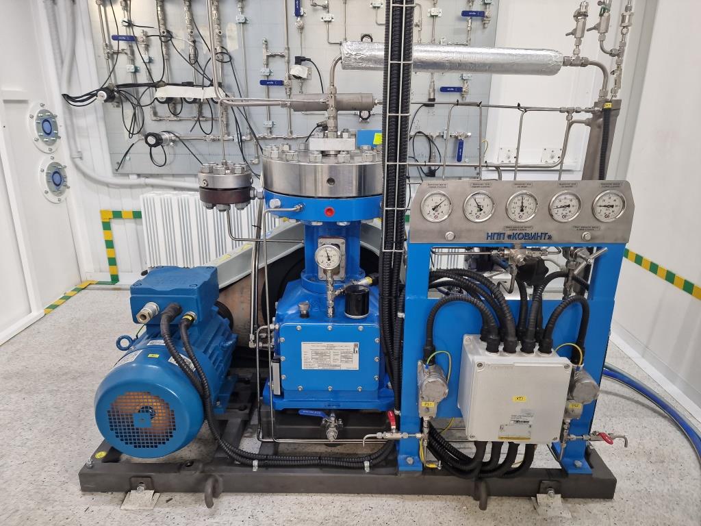
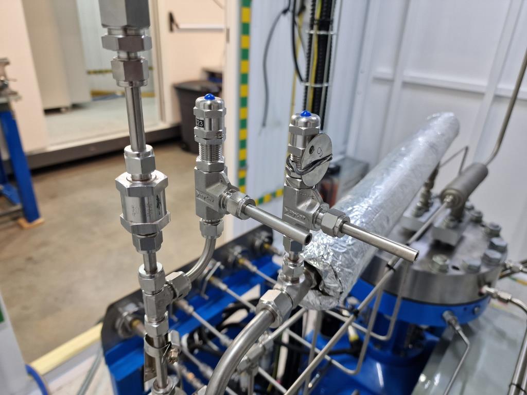
Each compressor has inlet and outlet gas pressure sensors. One more pressure sensor and pressure gauge are installed on lubrication system. We also install pressure gauges for parameters indication – inlet and outlet gas pressures, 1st and 2nd stages oil pressure, 1st and 2nd stages gas pressure.
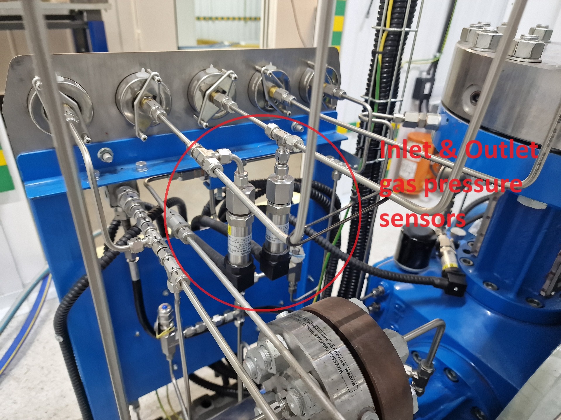
Inlet & Outlet gas pressure sensors
pressure gauges:
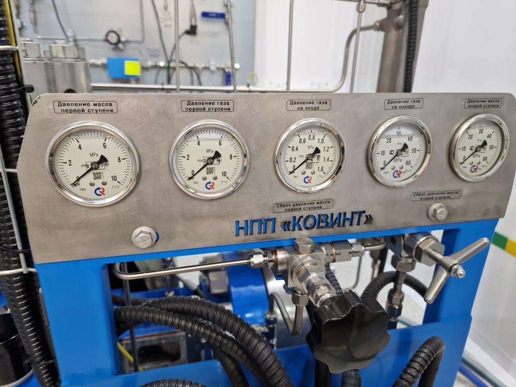
Pressure gauges
crankcase oil pressure gauge and sensor:
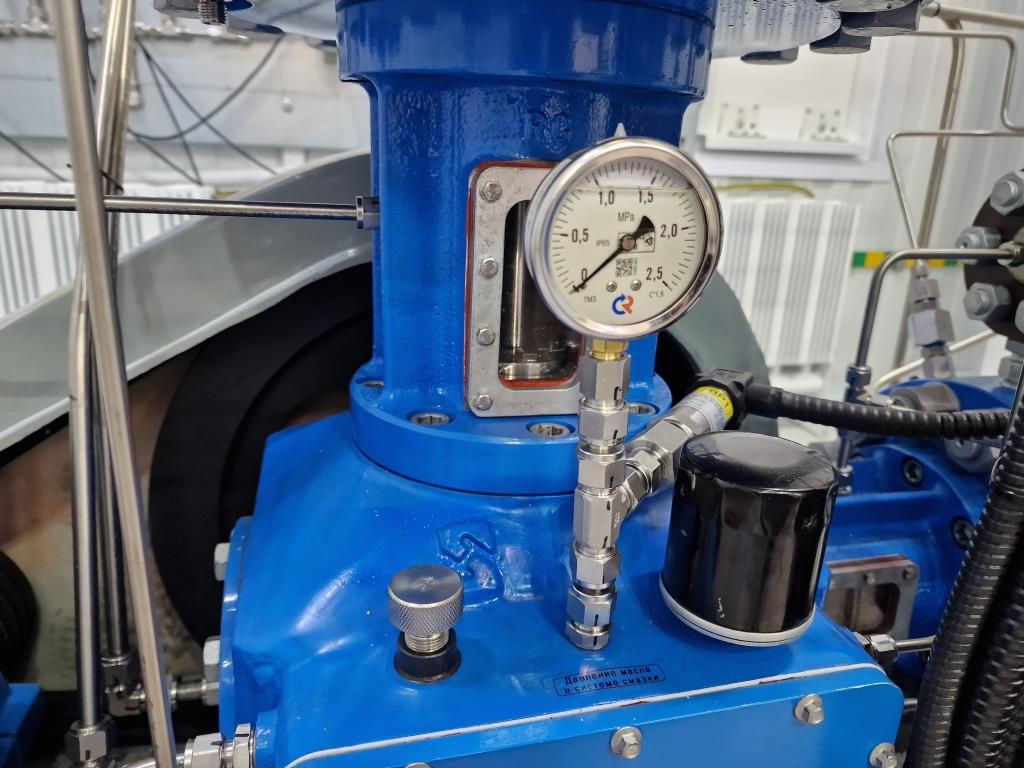
Crankcase oil pressure gauge and sensor
In the front you can see the wiring box, 2 pressure switches for diaphragm rupture detection, manual oil drop valves and gauge panel.
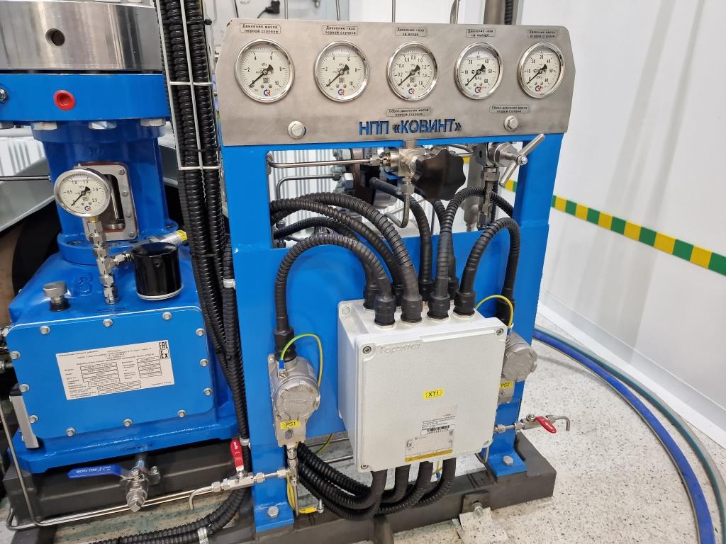
Gauge panel and wiring box
That compressor is driven by 7.5 kW motor with explosion proof.
The real electricity consumption is about 6 kW.
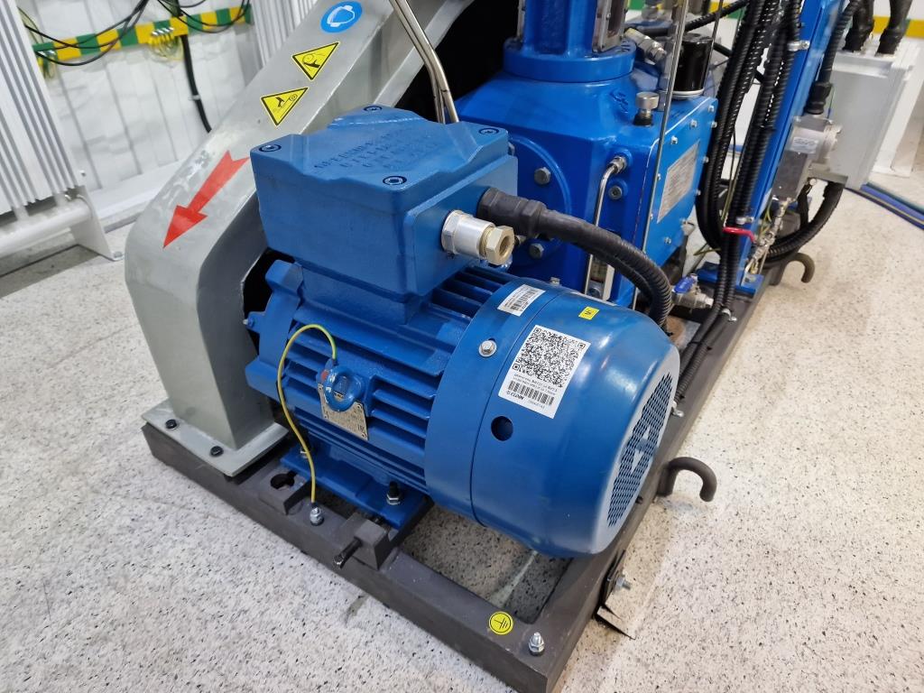
Motor
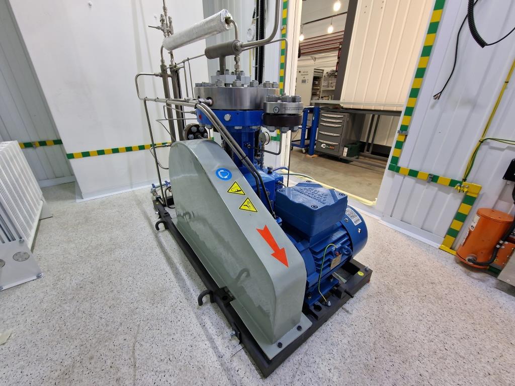
Compressor has v-belt drive.
There is special cover, which you can see right now, and anti-static belts under that cover.
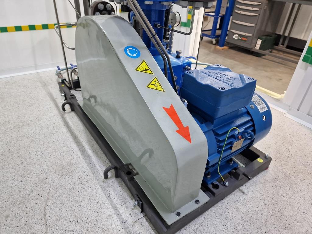
V-belt drive and cover
All compressor parts are placed on special base frame. The base frame has 4 holes for mounting.
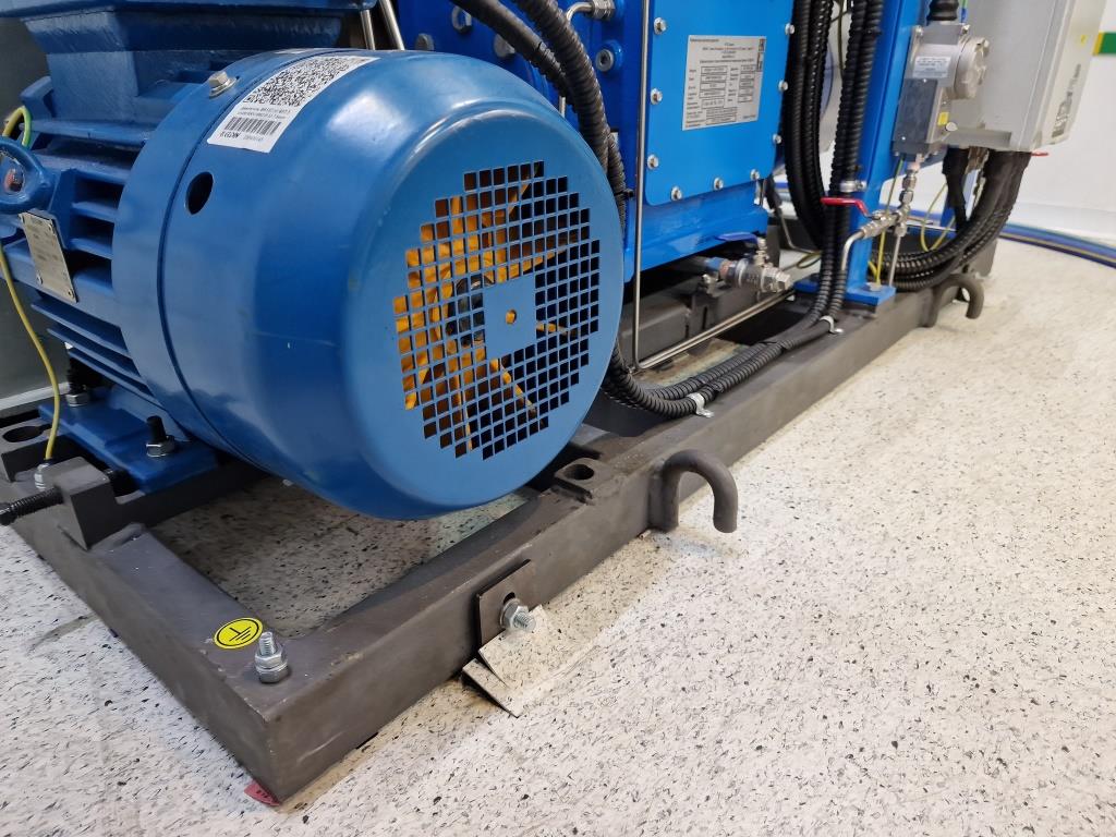
base frame
That compressor is water cooled. You can take water from your water circle or it’s possible to create the closed water system with radiator or chiller.
We recommend to use chiller because of stable parameters and perfect cooling.
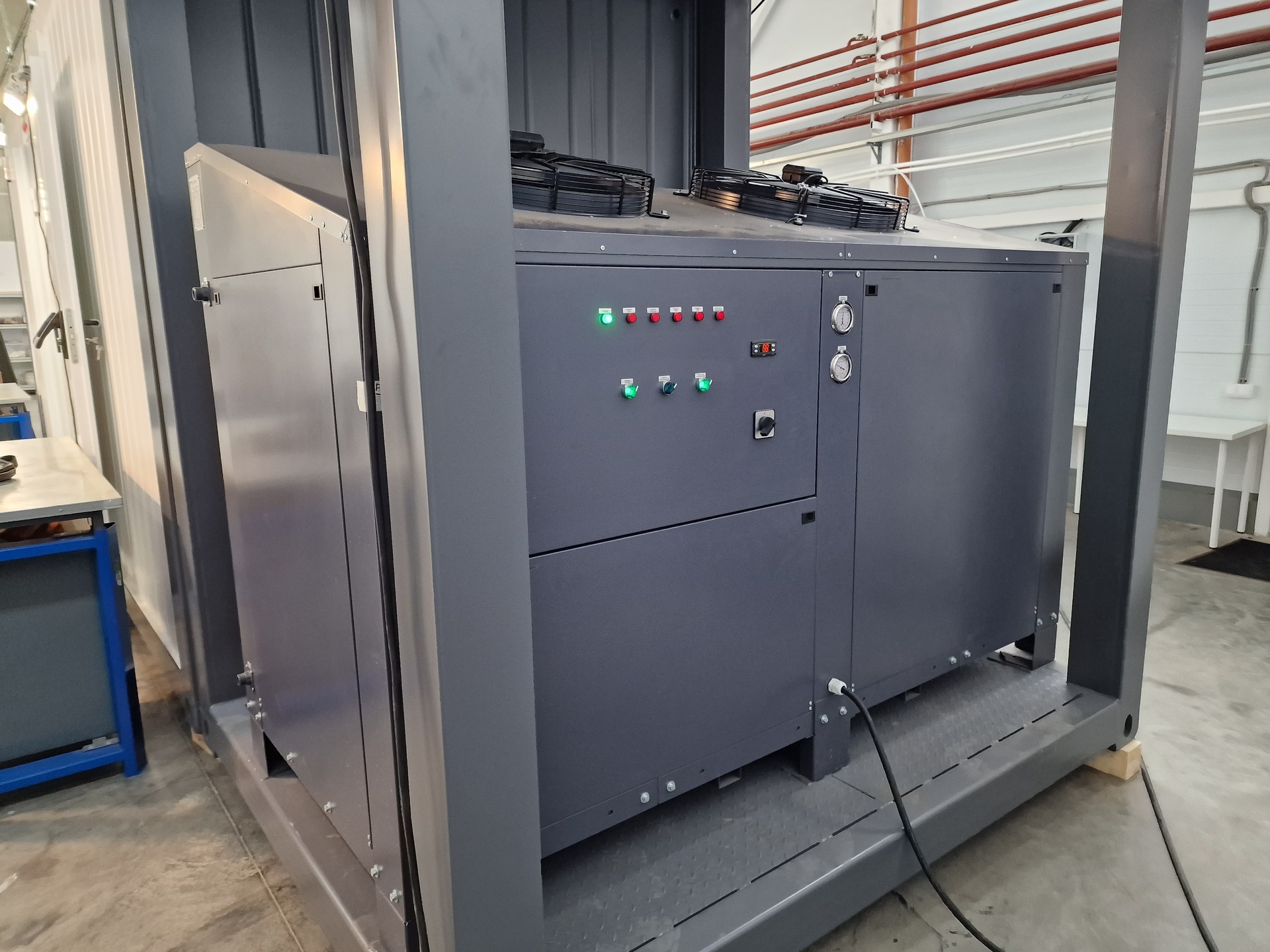
chiller
That model has auto oil pressure regulating valve as standard for auto mode.
Auto pressure regulating valve
and for the 2nd stage
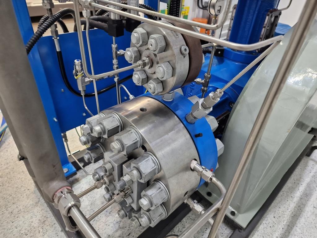
Auto pressure regulating valve 2nd stage
Each compressor is equipped with interstage and final delivery gas safety valves because of safety reasons.
Non-return valve and final gas temperature sensor are also installed as a standard.
Safety and non-return valves
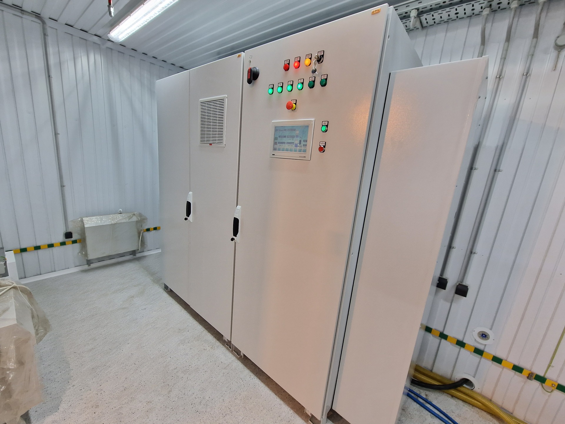
All compressors are equipped with control panel. It based on Siemens controllers and has all necessary equipment for stable and comfortable operation.
We develop and produce control panels by ourselves, that helps us to create solutions for remote control and so on.
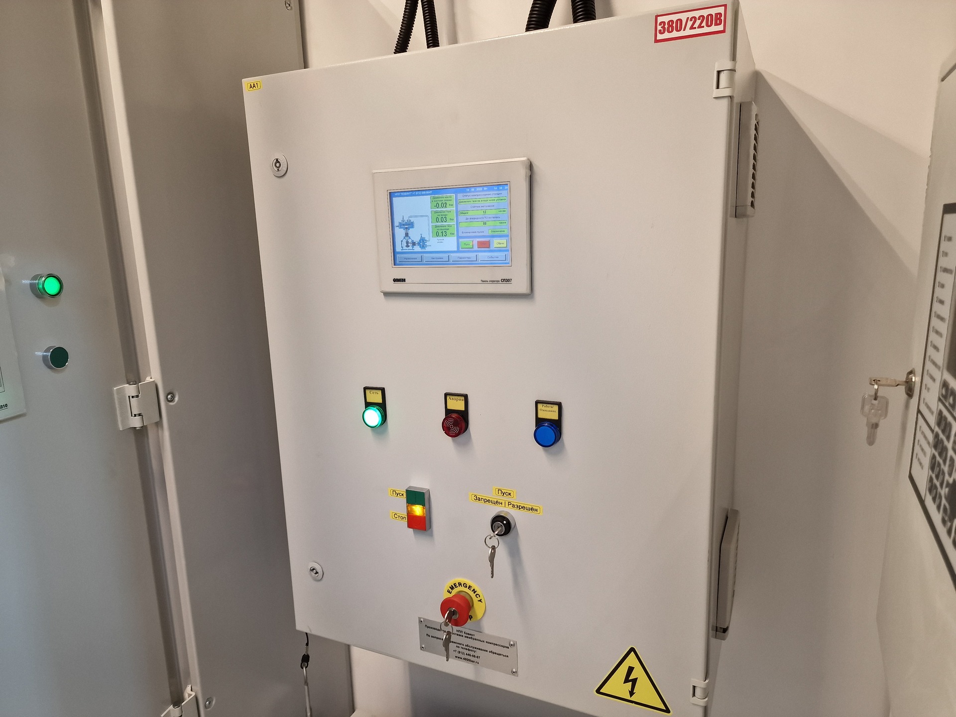
Control panel for hydrogen compressor
and inside
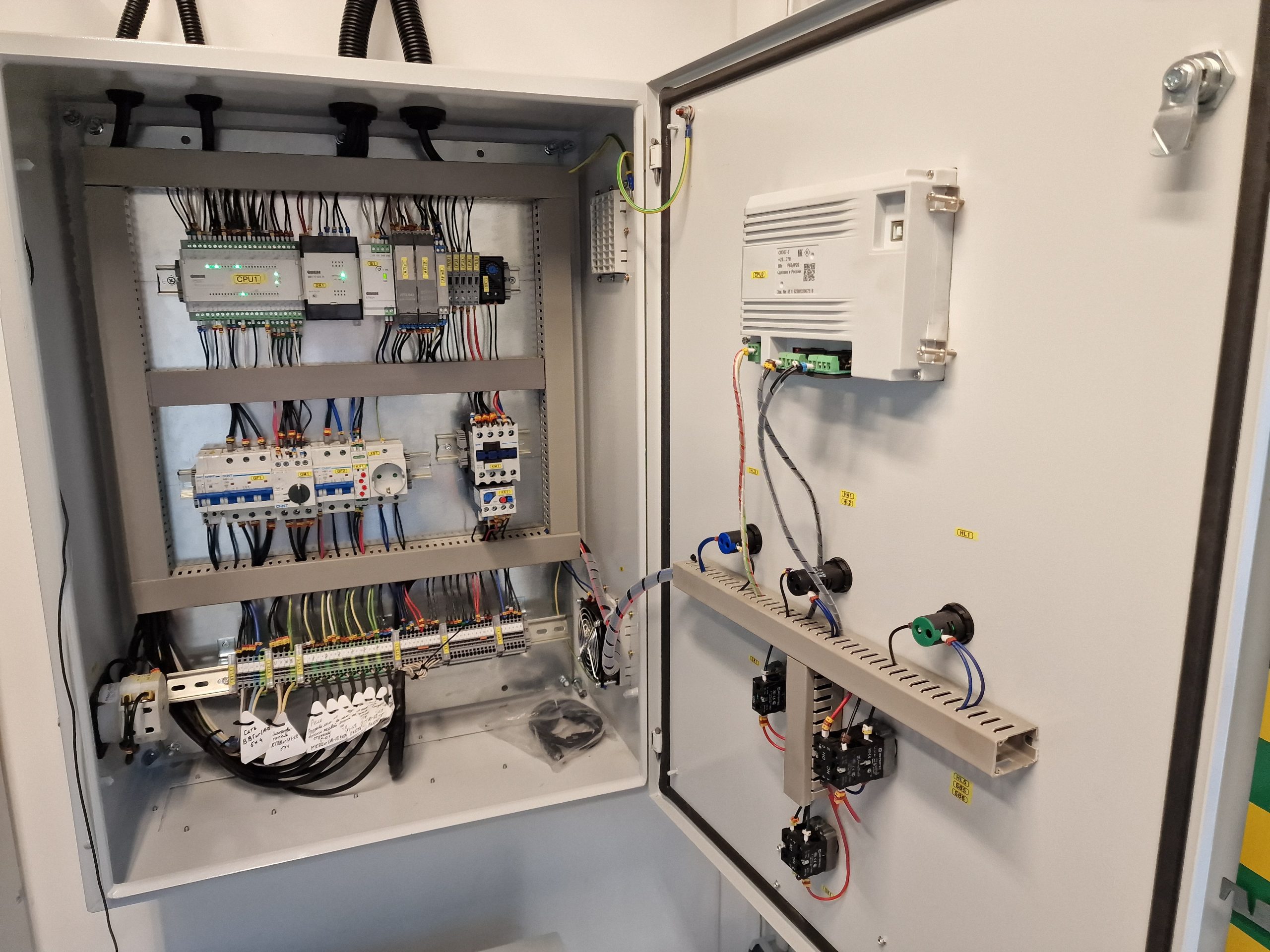
Control panel for hydrogen compressor (inside)
During the commissioning our engineer always checks all parameters and install the remote control if it’s necessary.
We also use the explosion proof START/STOP device with special buttons and lamps. It installed nearby compressor.
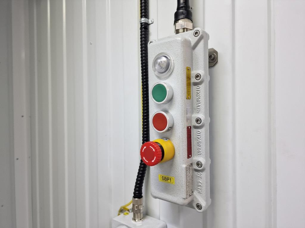
START – STOP device
Compressor is installed into standard 20 ft container. Container has all necessary equipment such as heating, lighting, pipelines, different alarms and so on.
It’s rated for using with ambient temperatures -40…+40 degree C.
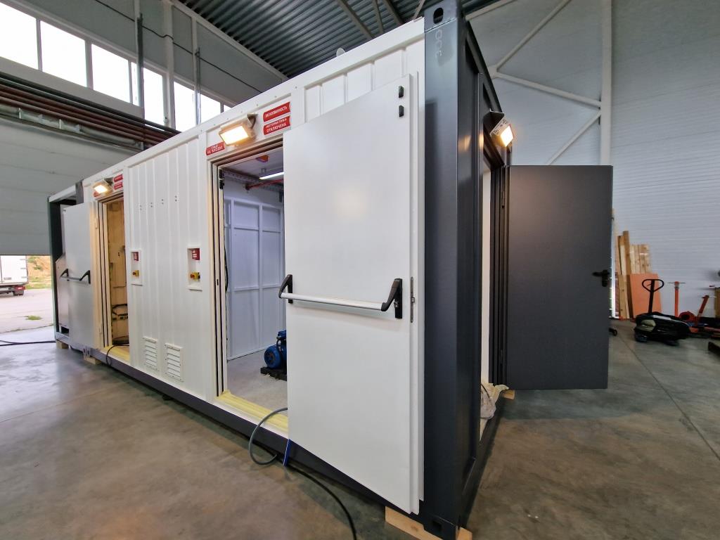
Container
Compressor is used together with high purity hydrogen generator and high pressure tanks with final pressure 400 bar.
Hydrogen generator
The final point of that hydrogen fueling station is high-flow and low-noise BUS & TRUCK dispenser. It also equipped with counter , display, different lamps and buttons and provides the fast and safe fueling.
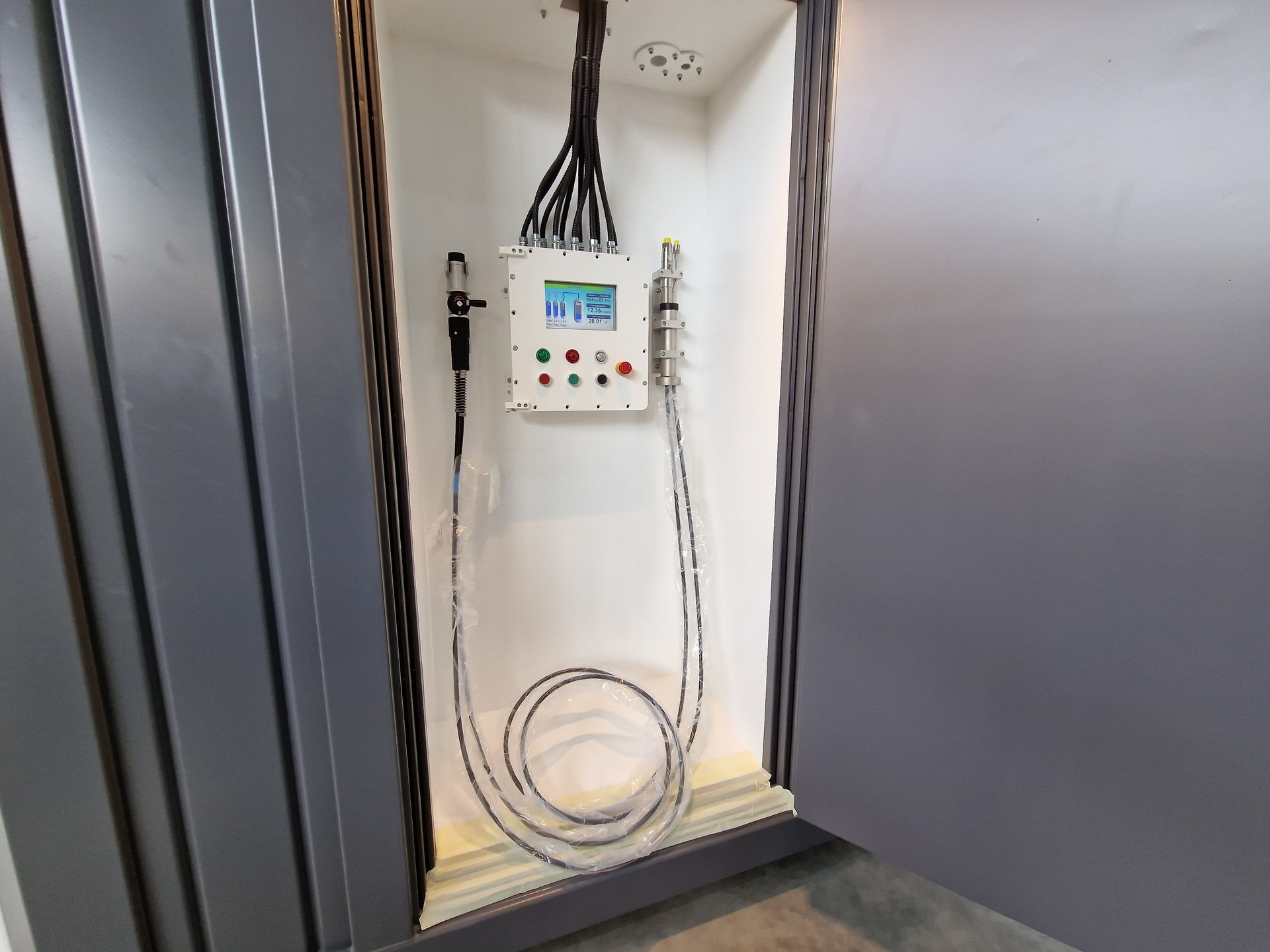
Dispenser
and
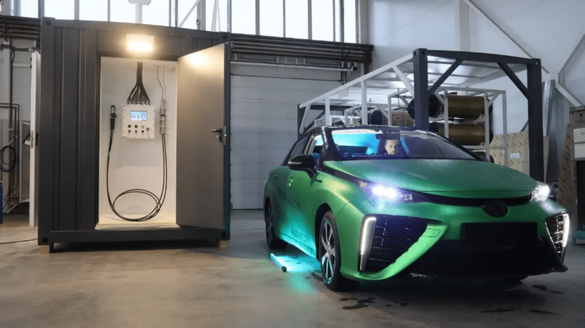
Car fueling
and for trucks and buses:
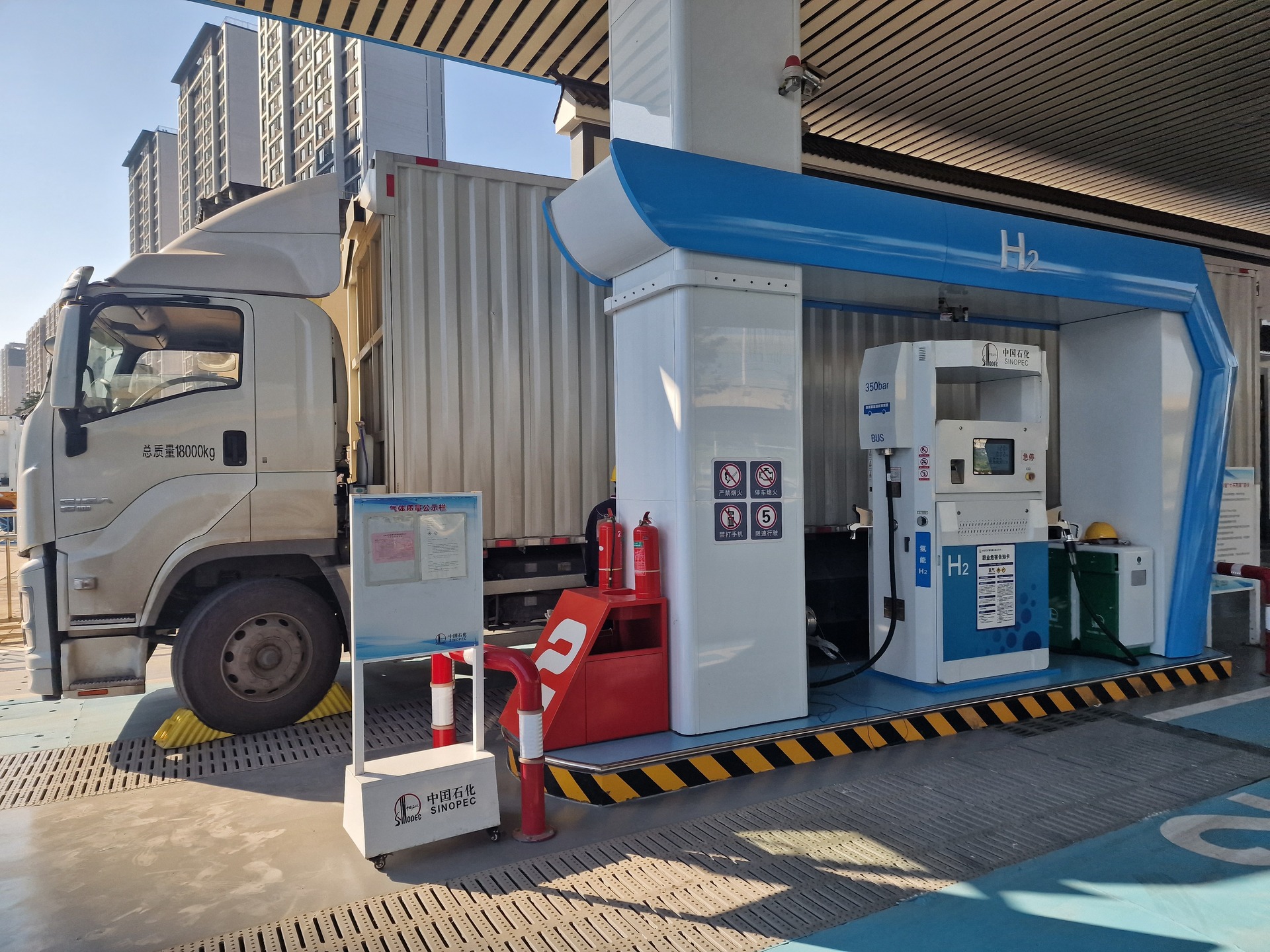
Trucks fueling
That’s all.
If you have any questions or you need some help with compressor selection, feel free to leave a comment below or send the message through the contact form on the page
I will answer within a couple of days.
Good luck.
Regards,
Konstantin Shirokikh